

DAMPER
FIRE DAMPER
HI AIR KOREA(HAK) A-Class FIRE & GAS DAMPERS for marine & offshore installations are type-certified based on Marine Equipment Directive 2014/90/EU and IMO Res. MSC.307(88). These dampers can be also supplied with ATEX Directive 2014/34/EU for explosive atmosphere installations
HAK H-Class FIRE & GAS DAMPERS are type-certified based on IMO 2010 FTP Code Part 3 with HC time-temperature curve specified in ISO 834-3.
Both A-Class and H-Class dampers can operate at temperatures between -40 ~ +60℃ but subject to change depending on the selected components. An open/close indication is visible on the damper enclosure side. The maximum duct pressure of damper operation is 5000 Pa. The local control switch or valves can be supplied as an option.
- FEATURES
A-CLASS
- HI AIR KOREA FIRE & GAS DAMPERS can be manufactured to fit both rectangular and circular ducts.
These dampers are equipped with quality frangible bulb to ensure that dampers will promptly close to eliminate the spread of fire & gas throughout ductwork. The standard frangible bulb shall break at a temperature of approx. 68°C. Other temperatures such as 93°C or 141°C can be provided upon request. - The FIRE & GAS DAMPERS are equipped with opposed blades that are designed to minimize pressure loss and noise on the air system.
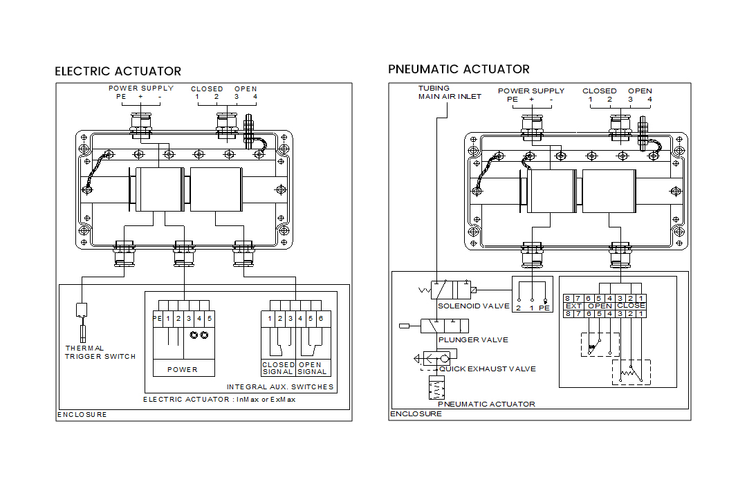
- FIRE & GAS DAMPERS can be fitted with electric or pneumatic actuators which shall include limit switches or proximity sensors that detect the position of the damper blades which in turn can be interfaced with monitoring and control system.
- The maximum size of the single type is 1,200 mm(W) and 1,400 mm(H). The pneumatic FIRE & GAS DAMPERS can be applied for mullion types, max. size of mullion types is 2,500 mm(W) and 2,100 mm(H).
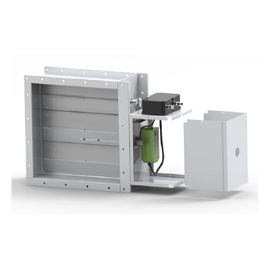
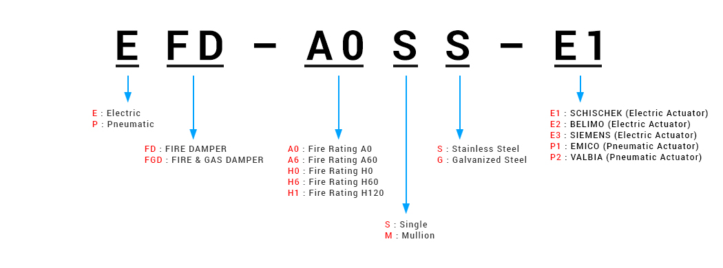
ELECTRIC FIRE & GAS DAMPER (EFD / EFGD)
-
The electric actuator requires 24 to 230 VAC/DC of electrical supply to open the damper blades.
The damper blades shall close when the power is cut-off.
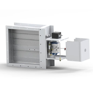
PNEUMATIC FIRE & GAS DAMPER (PFD / PFGD)
- The pneumatic actuator requires a supply of 5~8 bar of clean/dry instrument air to open the damper blades. The damper blades shall close when instrument air is cut-off or pressure is too low.
H-CLASS
- The maximum size of the single type is 1,200 mm(W) and 1,200 mm(H). The standard frangible bulb shall break at a temperature of approx. 68°C or 93°C. FIRE & GAS DAMPERS can be fitted with only pneumatic actuators.
PNEUMATIC FIRE & GAS DAMPER (PFD / PFGD)
- The pneumatic actuator requires a supply of 5~8 bar of clean/dry instrument air to open the damper blades. The damper blades shall close when instrument air is cut-off or pressure is too low.
LEAKAGE RATE
- The spring type side seal is provided to achieve the EN 1751 based leakage classes given below.
Damper sectional area Casing leakage Blade leakage ≥0.16㎡ Class B Class 3 <0.16㎡ Class B Class 2 CASING THICKNESS ACCORDING TO SOLAS
Dimensions (mm) Thickness (mm) W or H ≤ 300 3 300<W or H<760 4 W or H ≥760 5 - The standard casing thickness of the FIRE & GAS DAMPER is 3 mm. The casing thickness of 4~10 mm is available on request.
CERTIFICATION STATUS
Classification Class Type Casing material BV A-0 EC Type Examination Certificate A-Class : Carbon steel or
Stainless steel
H-Class : Stainless steelA-60 H-0 Type Approval Certificate H-60 H-120 DNV GL A-0 A-60 H-0 H-60 H-120 ABS or LR or KR A-0 A-60 ATEX
(DNV GL Nemko Presafe AS)A-0 EC Type Examination Certificate A-60 STANDARD CONSTRUCTION
Part Material Thickness Finishing Casing Carbon steel 3 ~ 10 mm Painted / Galvanized Stainless steel 3 ~ 10 mm Passivation Blades Galvanized steel 1.6 mm x 2 (Double skin) - Stainless steel 1.5 mm x 2 (Double skin) Passivation Shafts Carbon steel Φ19 Galvanized Stainless steel Φ19 Passivation Linkage Carbon steel 3 ~ 8 mm Painted / Galvanized Stainless steel 3 ~ 8 mm Passivation Linkage bar Carbon steel 3 ~ 8 mm Painted / Galvanized Stainless steel 3 ~ 8 mm Passivation Side seal Stainless steel 0.25 mm - Bearings (Bush type) Stainless steel or Brass - - WIRING DIAGRAM
- HI AIR KOREA FIRE & GAS DAMPERS can be manufactured to fit both rectangular and circular ducts.
- OPTIONS
- Local Control Switch
- Valve Board
- Black start air bottle
- ATEX Certificate
- Enclosure modification
- Witnessed leakage test
- CAPACITIES
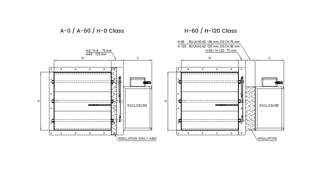
GENERAL ARRANGEMENT DRAWING
NOTES
- 1. Standard flange drilling is in accordance with ISO 15138:2007 ANNEX E
- 2. Circular type coaming is allowed only for A-Class FIRE & GAS DAMPERS with diameter not bigger than 400 mm.
- 3. Enclosure size "X" (If required)
TYPE "X" PNEUMATIC Min. 225 ㎜ / Max. 420㎜ ELECTRIC Min. 180 ㎜ / Max. 300㎜ WEIGHT FOR FIRE DAMPER
Weight (kg, Without actuator) for A-0 Class Height
(H, mm)Width (W, mm) 100 200 300 400 500 600 700 800 900 1000 1100 1200 100 8 10 12 16 18 21 23 25 28 30 37 40 200 10 13 16 19 22 25 28 30 33 36 43 46 300 13 16 19 23 26 29 32 35 38 42 49 53 400 17 21 24 27 31 34 38 41 45 48 56 60 500 20 23 27 31 35 39 42 46 50 54 62 66 600 23 27 31 36 40 44 48 52 56 60 69 74 700 26 30 35 39 44 48 53 57 61 66 75 80 800 29 34 39 44 49 53 58 63 68 72 83 88 900 32 37 42 47 52 58 63 68 73 78 89 94 1000 36 41 46 52 57 63 68 74 79 85 96 101 1100 41 47 53 59 65 71 77 84 90 96 102 108 1200 44 50 57 63 69 76 82 89 95 101 108 114 1300 47 53 61 67 73 81 87 94 100 106 114 120 1400 50 56 65 71 77 86 92 99 105 111 120 126 - Weights above are with casing thickness of 3 mm.
- For A-60 Class, insulation weight shall be added to the above figures.
- DOCUMENTS